


A New Wrist–Forearm Rehabilitation Protocol Integrating Human Biomechanics and SVM-Based Machine Learning for Muscle Fatigue Estimation


Abstract
:1. Introduction
2. Materials and Methods
2.1. Mechanical Design and Model
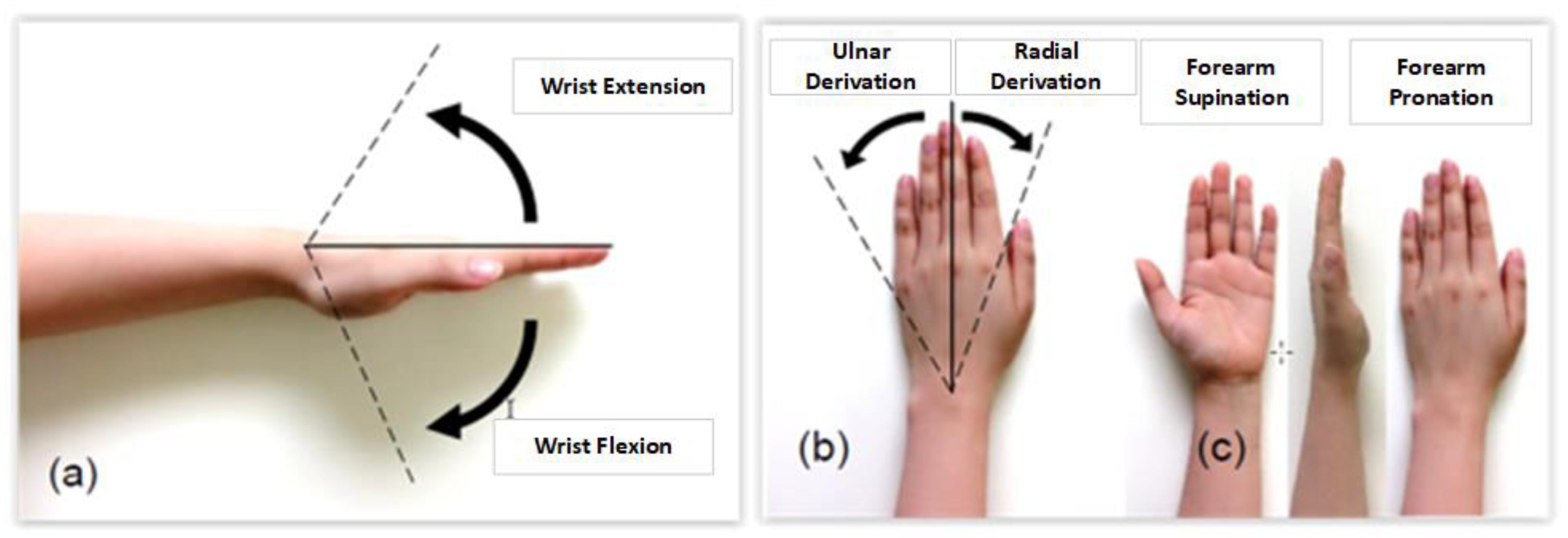
2.1.1. Review of the Range of Motion of the Human Hand
2.1.2. Robot Design
2.1.3. Robot Kinematics
2.2. Second-Order Mechanical Impedance Model of Wrist and Forearm Rotations
2.3. Control Architecture Design
2.3.1. EMG Acquisition, Pre-Processing, and Feature Extraction
2.3.2. LabVIEW-Based SVM Classifier for Muscle Fatigue Estimation
2.3.3. Defined Rehabilitation Process
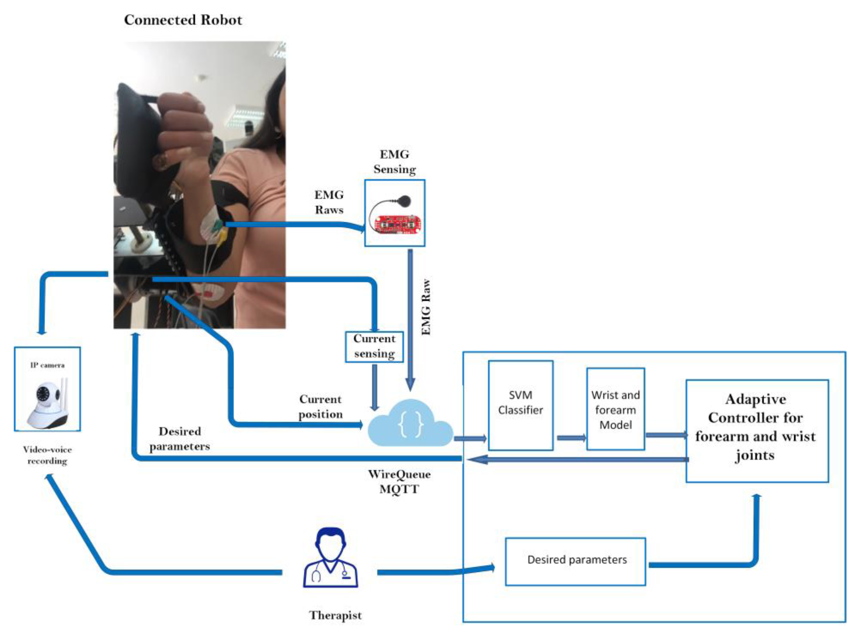
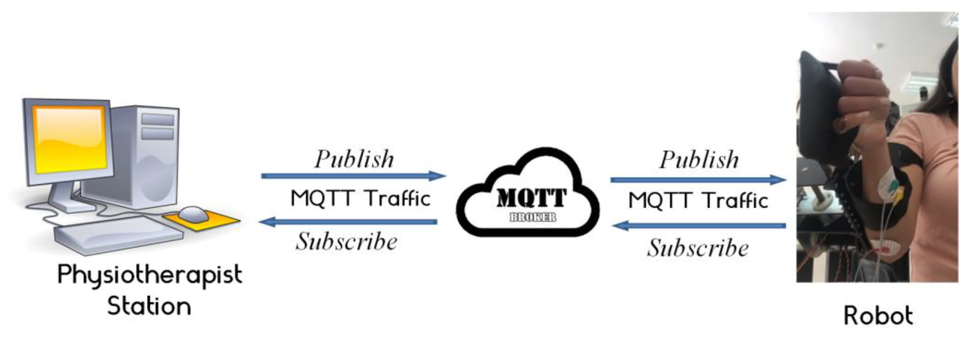
2.3.4. Tele-Rehabilitation Architecture
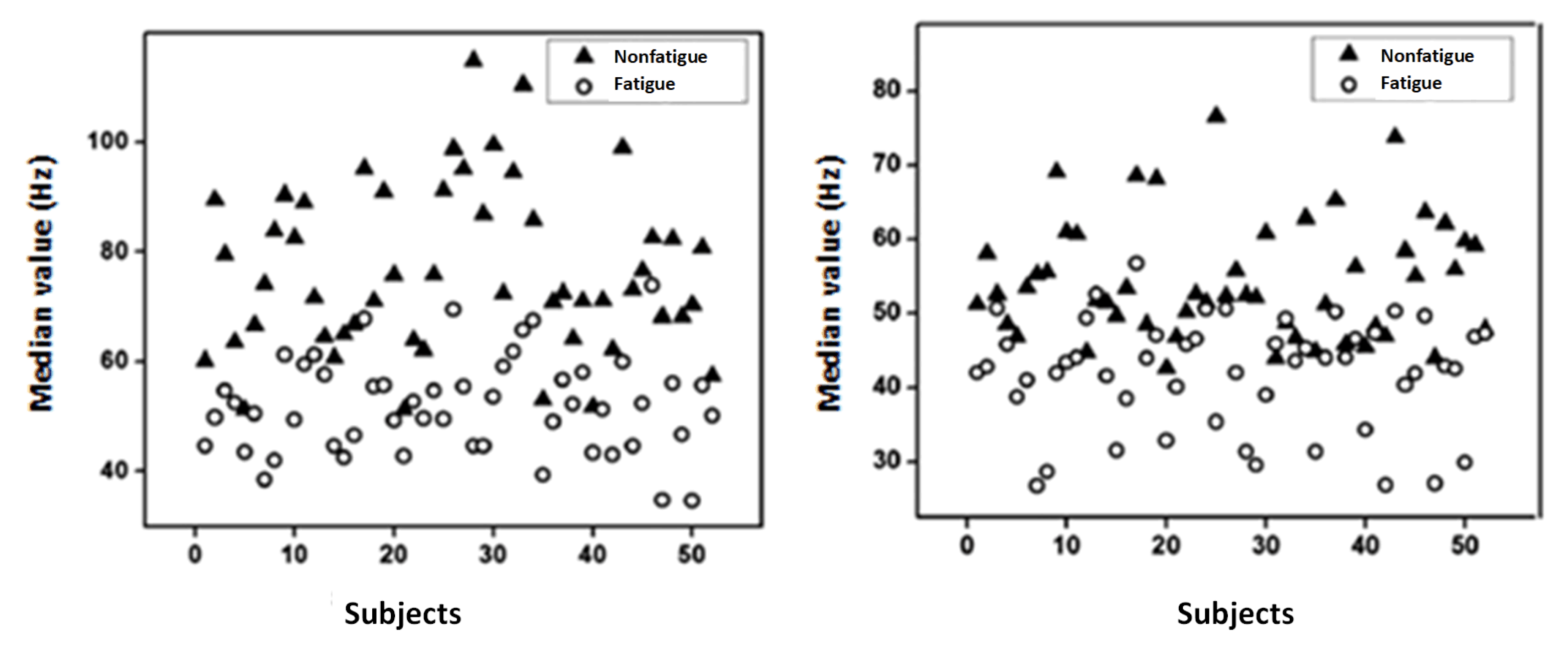
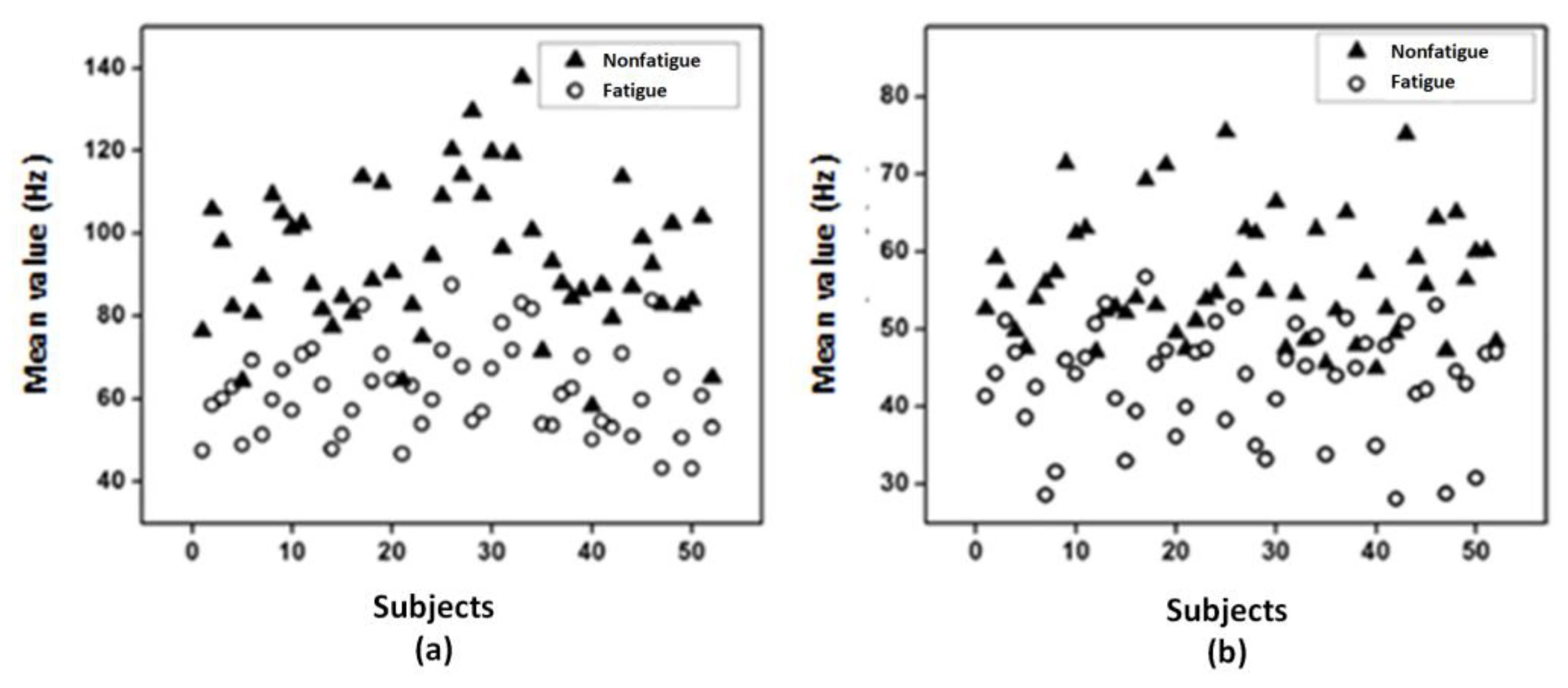
3. Results and Discussions
4. Conclusions
Author Contributions
Funding
Institutional Review Board Statement
Informed Consent Statement
Data Availability Statement
Acknowledgments
Conflicts of Interest
References
- Samaee, S.; Kobravi, H.R. Predicting the occurrence of wrist tremor based on electromyography using a hidden Markov model and entropy based learning algorithm. Biomed. Signal Process. Control. 2020, 57, 101739. [Google Scholar] [CrossRef]
- Moshaii, A.A.; Moghaddam, M.M.; Niestanak, V.D. Fuzzy sliding mode control of a wearable rehabilitation robot for wrist and finger. Ind. Robot. 2019, 46, 839–850. [Google Scholar] [CrossRef]
- Mazzoleni, S.; Tran, V.-D.; Dario, P.; Posteraro, F. Wrist Robot-Assisted Rehabilitation Treatment in Subacute and Chronic Stroke Patients: From Distal-to-Proximal Motor Recovery. IEEE Trans. Neural Syst. Rehabil. Eng. 2018, 26, 1889–1896. [Google Scholar] [CrossRef] [PubMed]
- Bauer, G.; Pan, Y.-J. Review of Control Methods for Upper Limb Telerehabilitation with Robotic Exoskeletons. IEEE Access 2020, 8, 203382–203397. [Google Scholar] [CrossRef]
- Rozevink, S.G.; van der Sluis, C.K.; Garzo, A.; Keller, T.; Hijmans, J.M. HoMEcare aRm rehabiLItatioN (MERLIN): Telerehabilitation using an unactuated device based on serious games improves the upper limb function in chronic stroke. J. Neuroeng. Rehabil. 2021, 18, 48. [Google Scholar] [CrossRef]
- Manjunatha, H.; Pareek, S.; Jujjavarapu, S.S.; Ghobadi, M.; Kesavadas, T.; Esfahani, E.T. Upper Limb Home-Based Robotic Rehabilitation During COVID-19 Outbreak. Front. Robot. AI 2021, 8, 612834. [Google Scholar] [CrossRef]
- Mocan, B.; Mocan, M.; Fulea, M.; Murar, M.; Feier, H. Home-Based Robotic Upper Limbs Cardiac Telerehabilitation System. Int. J. Environ. Res. Public Health 2022, 19, 11628. [Google Scholar] [CrossRef]
- Knepley, K.D.; Mao, J.Z.; Wieczorek, P.; Okoye, F.O.; Jain, A.P.; Harel, N.Y. Impact of Telerehabilitation for Stroke-Related Deficits. Telemed. E-Health 2021, 27, 239–246. [Google Scholar] [CrossRef]
- Charles, S.K.; Hogan, N. Dynamics of wrist rotations. J. Biomech. 2011, 44, 614–621. [Google Scholar] [CrossRef]
- Peaden, A.W.; Charles, S.K. Dynamics of wrist and forearm rotations. J. Biomech. 2014, 47, 2779–2785. [Google Scholar] [CrossRef]
- Dobryakova, E.; Genova, H.M.; DeLuca, J.; Wylie, G.R. The Dopamine Imbalance Hypothesis of Fatigue in Multiple Sclerosis and Other Neurological Disorders. Front. Neurol. 2015, 6, 52. [Google Scholar] [CrossRef]
- Karthick, P.; Ghosh, D.M.; Ramakrishnan, S. Surface electromyography based muscle fatigue detection using high-resolution time-frequency methods and machine learning algorithms. Comput. Methods Programs Biomed. 2018, 154, 45–56. [Google Scholar] [CrossRef]
- Phinyomark, A.; Phukpattaranont, P.; Limsakul, C. Feature reduction and selection for EMG signal classification. Expert Syst. Appl. 2012, 39, 7420–7431. [Google Scholar] [CrossRef]
- Phinyomark, A.; Quaine, F.; Charbonnier, S.; Serviere, C.; Tarpin-Bernard, F.; Laurillau, Y. EMG feature evaluation for improving myoelectric pattern recognition robustness. Expert Syst. Appl. 2013, 40, 4832–4840. [Google Scholar] [CrossRef]
- Phinyomark, A.; Scheme, E. EMG Pattern Recognition in the Era of Big Data and Deep Learning. Big Data Cogn. Comput. 2018, 2, 21. [Google Scholar] [CrossRef]
- Keemink, A.Q.L.; Van Der Kooij, H.; Stienen, A.H.A. Admittance control for physical human–robot interaction. Int. J. Robot. Res. 2018, 37, 1421–1444. [Google Scholar] [CrossRef]
- Ben Abdallah, I.; Bouteraa, Y.; Rekik, C. Kinect-Based Sliding Mode Control for Lynxmotion Robotic Arm. Adv. Human-Comput. Interact. 2016, 2016, 1–10. [Google Scholar] [CrossRef]
- Vogel, J.; Castellini, C.; van der Smagt, P. EMG-Based Teleoperation and Manipulation with the DLR LWR-III. In Proceedings of the IEEE/RSJ International Conference on Intelligent Robots and Systems, San Francisco, CA, USA, 25–30 September 2011. [Google Scholar] [CrossRef]
- Meng, Q.; Zhang, J.; Yang, X. Virtual Rehabilitation Training System Based on Surface EMG Feature Extraction and Analysis. J. Med. Syst. 2019, 43, 48. [Google Scholar] [CrossRef]
- Krebs, H.; Palazzolo, J.; DiPietro, L.; Ferraro, M.; Krol, J.; Rannekleiv, K.; Volpe, B.; Hogan, N. Rehabilitation Robotics: Performance-Based Progressive Robot-Assisted Therapy. Auton. Robot. 2003, 15, 7–20. [Google Scholar] [CrossRef]
- Bi, L.; Feleke, A.; Guan, C. A review on EMG-based motor intention prediction of continuous human upper limb motion for human-robot collaboration. Biomed. Signal Process. Control 2019, 51, 113–127. [Google Scholar] [CrossRef]
- Yamamoto, I.; Matsui, M.; Higashi, T.; Iso, N.; Hachisuka, K.; Hachisuka, A. Wrist Rehabilitation Robot System and Its Effectiveness for Patients. Sensors Mater. 2018, 30, 1825. [Google Scholar] [CrossRef]
- Mashayekhi, M.; Moghaddam, M.M. EMG-driven fatigue-based self-adapting admittance control of a hand rehabilitation robot. J. Biomech. 2022, 138, 111104. [Google Scholar] [CrossRef] [PubMed]
- Wang, H.; Chen, P.; Li, Y.; Sun, B.; Liao, Z.; Niu, B.; Niu, J. New Rehabilitation Assessment Method of the End-Effector Finger Rehabilitation Robot Based on Multi-Sensor Source. Healthcare 2021, 9, 1251. [Google Scholar] [CrossRef] [PubMed]
- Kanal, V.; Abujelala, M.; Brady, J.; Wylie, G.; Makedon, F. Adaptive robotic rehabilitation using muscle fatigue as a trigger. In Proceedings of the 16th EAI International Conference on Mobile and Ubiquitous Systems: Computing, Networking and Services, Houston, TX, USA, 12–14 November 2019. [Google Scholar]
- Thomas, K.; Hjalmarsson, C.; Mullis, R.; Mant, J. Conceptualising post-stroke fatigue: A cross-sectional survey of UK-based physiotherapists and occupational therapists. BMJ Open 2019, 9, e033066. [Google Scholar] [CrossRef]
- Xu, W.; Chu, B.; Rogers, E. Iterative learning control for robotic-assisted upper limb stroke rehabilitation in the presence of muscle fatigue. Control. Eng. Pract. 2014, 31, 63–72. [Google Scholar] [CrossRef]
- Telegenov KZeinullin MTursynbek IOmarkulov, N.; Shintemirov, A. Preliminary mechanical design of NU-Wrist: A 3-DOF selfaligning Wrist rehabilitation robot. In Proceedings of the IEEE International Conference on Biomedical Robotics and Biomechatronics (BioRob), Singapore, 26–29 June 2016; pp. 962–967. [Google Scholar] [CrossRef]
- Phan, H.L.; Kim, J.P.; Kim, K.; Hwang, C.H.; Koo, K.-I. Wrist Rehabilitation System Using Augmented Reality for Hemiplegic Stroke Patient Rehabilitation: A Feasibility Study. Appl. Sci. 2019, 9, 2892. [Google Scholar] [CrossRef]
- Gayda, M.; Merzouk, A.; Choquet, D.; Ahmaidi, S. Assessment of skeletal muscle fatigue in men with coronary artery disease using surface electromyography during isometric contraction of quadriceps muscles. Arch. Phys. Med. Rehabil. 2005, 86, 210–215. [Google Scholar] [CrossRef]
- Bouteraa, Y.; Abdallah, I.B.; Elmogy, A.; Ibrahim, A.; Tariq, U.; Ahmad, T. A fuzzy logic architecture for rehabilitation robotic systems. Int. J. Comput. Commun. Control 2020, 15, 3814. [Google Scholar] [CrossRef]
- Squeri, V.; Masia, L.; Giannoni, P.; Sandini, G.; Morasso, P. Wrist rehabilitation in chronic stroke patients by means of adaptive, progressive robot-aided therapy. IEEE Trans. Neural Syst. Rehabil. Eng. 2014, 22, 312–325. [Google Scholar] [CrossRef]
- Marshall, M.M.; Mozrall, J.R.; Shealy, J.E. The effects of complex wrist and forearm posture on wrist range of motion. Hum. Factors J. Hum. Factors Ergon. Soc. 1999, 41, 205–213. [Google Scholar] [CrossRef]
- John MR, S.; Thomas, N.; Sivakumar VP, R. Design and Development of Cable Driven Upper Limb Exoskeleton for Arm Rehabilitation. Int. J. Sci. Eng. Res. 2016, 7, 1432–1440. [Google Scholar]
- Keller, U.; van Hedel, H.J.A.; Klamroth-Marganska, V.; Riener, R. ChARMin: The First Actuated Exoskeleton Robot for Pediatric Arm Rehabilitation. IEEE/ASME Trans. Mechatron. 2016, 21, 2201–2213. [Google Scholar] [CrossRef]
- Brigstocke, G.; Hearnden, A.; Holt, C.; Whatling, G. The functional range of movement of the human wrist. J. Hand Surg. 2013, 38, 554–556. [Google Scholar] [CrossRef]
- Drake, W.B.; Charles, S.K. Passive Stiffness of Coupled Wrist and Forearm Rotations. Ann. Biomed. Eng. 2014, 42, 1853–1866. [Google Scholar] [CrossRef]
- de Leva, P. Adjustments to Zatsiorsky-Seluyanov’s segment inertia parameters. J. Biomech. 1996, 29, 1223–1230. [Google Scholar] [CrossRef]
- Gielen, C.C.; Houk, J.C. Nonlinear viscosity of human wrist. J. Neurophysiol. 1984, 52, 553–569. [Google Scholar] [CrossRef]
- Oskoei, M.A.; Hu, H. GA-based Feature Subset Selection for Myoelectric Classification. In Proceedings of the IEEE International Conference on Robotics Biomimetics, Kunming, China, 17–20 December 2006; pp. 1465–1470. [Google Scholar] [CrossRef]
- Venugopal, G.; Navaneethakrishna, M.; Ramakrishnan, S. Extraction and analysis of multiple time window features associated with muscle fatigue conditions using sEMG signals. Expert Syst. Appl. 2014, 41, 2652–2659. [Google Scholar] [CrossRef]
- Stegeman, D.; Hermens, H. Standards for Surface Electromyography: The European Project Surface EMG for Non-Invasive 355 Assessment of Muscles (SENIAM); Roessingh Research and Development: Enschede, The Netherlands, 2007; Volume 10, pp. 8–12. [Google Scholar]
- Avci, E. A new intelligent diagnosis system for the heart valve diseases by using genetic-SVM classifier. Expert Syst. Appl. 2009, 36, 10618–10626. [Google Scholar] [CrossRef]
- Merletti, R.; Parker, P.J. (Eds.) Electromyography: Physiology, Engineering, and Non-Invasive Applications; John Wiley & Sons: New, York, NY, USA, 2004; Volume 11. [Google Scholar]
- Mugnosso, M.; Marini, F.; Holmes, M.; Morasso, P.; Zenzeri, J. Muscle fatigue assessment during robot-mediated movements. J. Neuroeng. Rehabil. 2018, 15, 119. [Google Scholar] [CrossRef]
- Thacham Poyil, A.; Steuber, V.; Amirabdollahian, F. Adaptive robot mediated upper limb training using electromyogram-based muscle fatigue indicators. PLoS ONE 2020, 15, e0233545. [Google Scholar] [CrossRef]
- Mugnosso, M.; Zenzeri, J.; Hughes, C.M.L.; Marini, F. Coupling Robot-Aided Assessment and Surface Electromyography (sEMG) to Evaluate the Effect of Muscle Fatigue on Wrist Position Sense in the Flexion-Extension Plane. Front. Hum. Neurosci. 2019, 13, 396. [Google Scholar] [CrossRef] [PubMed]
- Li, D.; Chen, C. Research on exercise fatigue estimation method of Pilates rehabilitation based on ECG and sEMG feature fusion. BMC Med. Inform. Decis. Mak. 2022, 22, 67. [Google Scholar] [CrossRef] [PubMed]
- Papakostas, M.; Kanal, V.; Abujelala, M.; Tsiakas, K.; Makedon, F. Physical fatigue detection through EMG wearables and subjective user reports: A machine learning approach towards adaptive rehabilitation. In Proceedings of the 12th ACM International Conference on Pervasive Technologies Related to Assistive Environments, Rhodes, Greece, 5–7 June 2019. [Google Scholar]
- Wang, W.; Li, H.; Kong, D.; Xiao, M.; Zhang, P. A novel fatigue detection method for rehabilitation training of upper limb exoskeleton robot using multi-information fusion. Int. J. Adv. Robot. Syst. 2020, 17, 172988142097429. [Google Scholar] [CrossRef]


| Actuators | Weight | Torque |
|---|---|---|
| HS-805BB Servomotor | 152 g | 25 Kg.cm |
| NEMA 23 stepper motor | 500 g | 19 Kg.cm |
| Joints | Motion | Workspace |
|---|---|---|
| Shoulder {1} | Flexion/Extension | 0°/140° |
| Elbow {2} | Flexion/Extension | 120°/0° |
| Forearm {4} | Pronation/Supination | −85°/+85° |
| Wrist {3} | Ulnar/Radial deviation | −30°/+20° |
| Flexion/Extension | +60°/−50° |
| Joint (i) | αi−1 | ai−1 | di | θi |
|---|---|---|---|---|
| 1 | 0 | 0 | ds | θ1 |
| 2 | 0 | 0 | de | θ2 |
| 3 | 0 | 0 | dw | θ3 |
| 4 | π/2 | 0 | 0 | θ4 |
| A | |
| B | |
| C | |
| D | |
| E | 0 |
| F | |
| G | |
| H | |
| I |
| Frequency Domain Features Extraction | Classifier | Sensitivity (%) | Specificity (%) | Accuracy (%) |
|---|---|---|---|---|
| MNF | SVM | 73.25 | 85.65 | 91.32 |
| MNP | 82.12 | 89.45 | 92.62 |
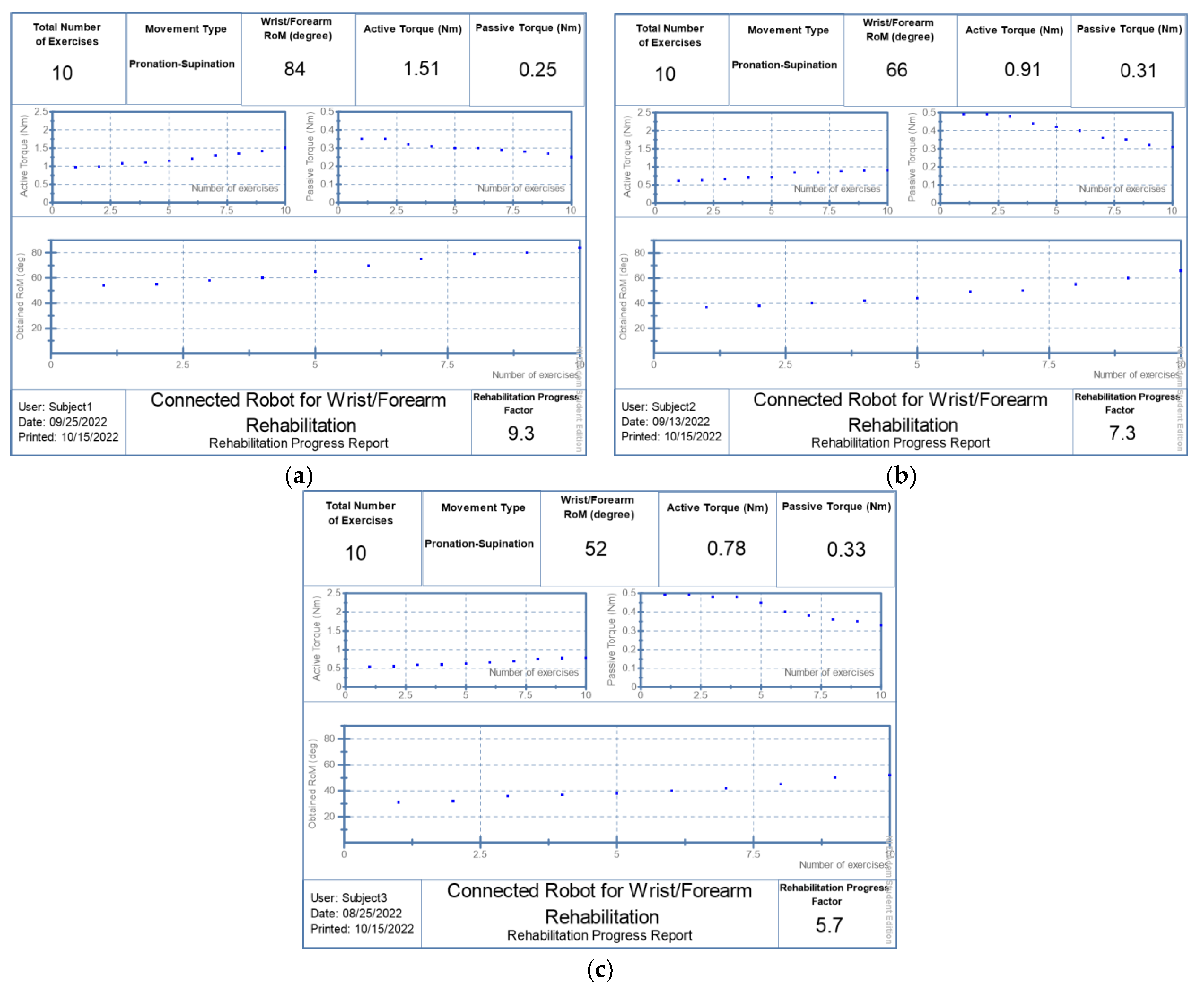
| Subject Number | Initial Parameters–Obtained Parameters | ||
|---|---|---|---|
| RoM (Degree) | Active Torque (Nm) | Passive Torque (Nm) | |
| 1 | 54 to 84 | 0.97 to 1.51 | 0.35 to 0.25 |
| 2 | 37 to 66 | 0.61 to 0.91 | 0.49 to 0.31 |
| 3 | 31 to 52 | 0.54 to 0.78 | 0.45 to 0.33 |
Disclaimer/Publisher’s Note: The statements, opinions and data contained in all publications are solely those of the individual author(s) and contributor(s) and not of MDPI and/or the editor(s). MDPI and/or the editor(s) disclaim responsibility for any injury to people or property resulting from any ideas, methods, instructions or products referred to in the content. |
© 2023 by the authors. Licensee MDPI, Basel, Switzerland. This article is an open access article distributed under the terms and conditions of the Creative Commons Attribution (CC BY) license (https://creativecommons.org/licenses/by/4.0/).
Share and Cite
Bouteraa, Y.; Abdallah, I.B.; Boukthir, K. A New Wrist–Forearm Rehabilitation Protocol Integrating Human Biomechanics and SVM-Based Machine Learning for Muscle Fatigue Estimation. Bioengineering 2023, 10, 219. https://doi.org/10.3390/bioengineering10020219
Bouteraa Y, Abdallah IB, Boukthir K. A New Wrist–Forearm Rehabilitation Protocol Integrating Human Biomechanics and SVM-Based Machine Learning for Muscle Fatigue Estimation. Bioengineering. 2023; 10(2):219. https://doi.org/10.3390/bioengineering10020219
Chicago/Turabian StyleBouteraa, Yassine, Ismail Ben Abdallah, and Khalil Boukthir. 2023. "A New Wrist–Forearm Rehabilitation Protocol Integrating Human Biomechanics and SVM-Based Machine Learning for Muscle Fatigue Estimation" Bioengineering 10, no. 2: 219. https://doi.org/10.3390/bioengineering10020219