
Related Manuals for Velleman DVM990BL


Summary of Contents for Velleman DVM990BL
- Page 1 DVM990BL DIGITAL MULTIMETER MULTIMETRE DIGITAL OPERATING MANUAL MANUEL D’UTILISATION DIGITALE MULTIMETER DIGITALES MULTIMETER BEDIENINGSHANDLEIDING BEDIENUNGSANLEITUNG MULTÍMETRO DÍGITAL MANUAL DEL USUARIO...
-
Page 2: Safety Information
1.2.4. Do not measure voltage if the voltage on the terminals exceeds 1000V above earth. 1.2.5. Always be careful when working with voltages above 60V DC or 30V AC rms, keep your fingers behind the probe barriers while measuring. DVM990BL VELLEMAN... - Page 3 1.4.5. Always set the power switch to the OFF position when the meter is not in use. 1.4.6. If the meter is to be stored for a long period of time, the batteries should be removed to prevent damage to the unit. DVM990BL VELLEMAN...
-
Page 4: Names Of Components
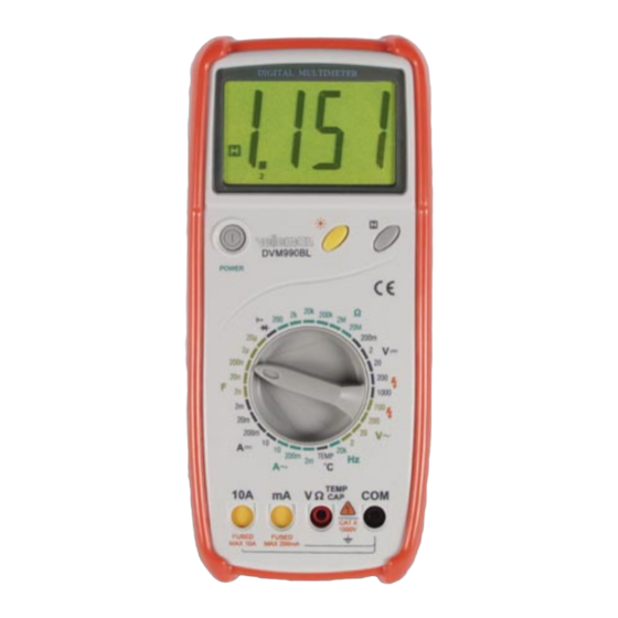
DESCRIPTION 2.1. NAMES OF COMPONENTS (1) LCD display (2) Power switch (POWER) (3) Black light switch ( (4) Data hold switch (H) (5) Rotary switch (6) Input socket (7) Case (8) Battery door (9) Brace (10) Screw DVM990BL VELLEMAN... -
Page 5: Function And Range Selector
Temperature factor: < 0.1 x accuracy / °C • Operating temperature: 0°C to 40°C (32°F to 104°F) • Storage temperature: -10°C to 50°C (10°F to 122°F) • Dimensions: 191 x 82 x 36mm (without holster) • Weight: approx. 280g (including battery) DVM990BL VELLEMAN... -
Page 6: Electrical Specifications
At low voltage range, the meter will show an unsteady reading when the test leads are not connected to the circuit. This is normal because the meter is very sensitive. When the test leads touch the circuit, you get the true reading. DVM990BL VELLEMAN... - Page 7 ± (1.0% of rdg + 5 digits) 200Mohm 100kohm ± (5.0% of (rdg - 10 digits) + 20 digits) Open Circuit Voltage: 200 Mohm range: 3V Other ranges: less than 700mV Overload protection: 250V DC or rms AC DVM990BL VELLEMAN...
- Page 8 Open circuit voltage: approximate 2.8V 3.2.9. Frequency Range Resolution Accuracy (% reading + digits) 20kHz 10Hz ± (1.5% of rdg + 10 digits) Overload Protection: 250V DC or rms AC Sensitivity: 200mV rms and input no more 10V rms DVM990BL VELLEMAN...
-
Page 9: Preparation For Measurement
" next to the input socket means that the input voltage or current should be less than that specified on the meter sticker in order to protect the interior circuit from damage. 4.3.3. Select the appropriate range for the item to be measured with the rotary switch. DVM990BL VELLEMAN... -
Page 10: Measuring Voltage
When the value to be measured is unknown beforehand, set the range selector to the highest position. " " means you cannot input a voltage that is more than 200mA or 10A depending on the socket used. Excess current will blow the fuse. DVM990BL VELLEMAN... -
Page 11: Measuring Resistance
(spare parts) into COM and V/Ω and put the capacitor leads into the two long sockets of the capacitor test unit, and capacitor testing is ready. WARNING To avoid electric shock, remove the test leads from the circuit under test before measuring the capacitance of a capacitor. DVM990BL VELLEMAN... -
Page 12: Measuring Temperature
V/Ω socket. (The polarity of the red lead is "+"). 4.10.2. Set the rotary switch to the position. 4.10.3. Connect the red lead to the anode, and the black lead to the cathode of the diode under test. 4.10.4. You can see the reading on the LCD. DVM990BL VELLEMAN... -
Page 13: Continuity Test
" indicator appears on the LCD display, it indicates that the battery should be replaced. 5.1.2. Loosen the screw fixing the battery door and remove it. 5.1.3. Replace the dead battery with a new one. 5.1.4. Put back the battery door. DVM990BL VELLEMAN... -
Page 14: Fuse Replacement
5.4.2. When measuring: attach it either to the back of the case or use it as a stand as illustrated in the cover. It has 3 different positions for easy reading. 5.4.3. Attach the stand to the top part of the meter and use as a hook for hanging. DVM990BL VELLEMAN... -
Page 15: Supplied With The Multimeter
• test leads • 9V battery type 6F22 or NEDA 1604 • fuse: F1 200mA/250V (Ø5 x 20mm) • fuse: F2 10A/250V (Ø5 x 20mm) • K-type thermocouple • operating manual OPTIONAL ACCESSORIES • capacitance test socket • holster DVM990BL VELLEMAN...