How to choose the right LNB for your satellite system.
STEP Electronics
STEP Electronics is a premier provider of satellite communication systems, equipment and services across APAC region.
Choosing the right LNB for the job will ensure trouble free operation for years to come.
Choosing the right LNB for the job will ensure trouble free operation for years to come.
Making an incorrect selection from the many and often confusing variants available can be costly and lead to unreliable operating and high system downtime.
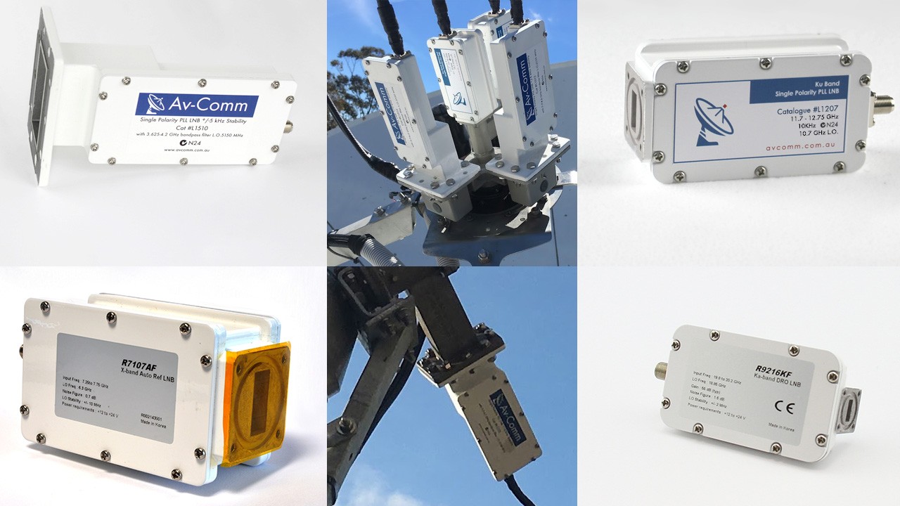
The LNB component of any satellite system is the device that amplifies the tiny satellite signal arriving at the dish from space and converts it to a manageable frequency range for transmission over coaxial cable in the 950-2050MHz range also referred to as L band. After a journey of 37,000km and enduring a path loss of around 200dB, the satellite signal arriving at the dish is very weak, hence the need for a large satellite dish to provide sufficient amplification.
To provide some perspective on how weak a typical geostationary satellite signal is when received on earth; a satellite transponder has ~60 Watts of RF transmission power available, imagine a 60 Watt light bulb 37,000km away and you’re trying to receive it, this is why you need big satellite dishes.
The internal frequency conversion process inside the LNB involves mixing the incoming frequency with a locally generated signal called a Local oscillator (L.O) and selecting the appropriate mixing product for transmission to a receiver or modem.
The most commonly encountered satellite bands are C and Ku bands, and more recently Ka band, although many other bands are utilised for military and other specialised satellites and missions.
Below is an explanation of the list of specifications likely to be encountered when selecting an LNB and an explanation on how to choose one for your application:
Input Frequency Range:
It's important to select an LNB with the correct input range for the required service. For television applications it might be necessary to have the capability to receive the entire available bandwidth of the satellite, whilst for other dedicated services, restricting the LNB bandwidth to a much narrower range would be advantageous.

C Band LNBs:
Over the last 10 years terrestrial communications services have slowly encroached on the originally allocated satellite bands. The most affected band is C band, where 5G services now occupy 3.4-3.7GHz in many countries. A 5G service can overload the LNB to the point where it is driven into compression, making reception of tiny satellite signals impossible.

So selecting an LNB with the correct bandwidth is important. If the desired service operates within the traditional 3.7-4.2GHz range, do not select an LNB with extended C band range of 3.4-4.2GHz. Such LNBs are prone to overload from terrestrial services. Determine the downlink frequency required either from the customer specifications of the satellite provider link budget, and select an LNB with the appropriate frequency coverage.
With the introduction of high powered 5G services operating adjacent to active satellite downlink frequencies, integration specialists now have the choice of selecting LNBs with even more restricted frequency range, as a method of eliminating interference. LNBs are now available that will only receive signals between 3.8-4.2 and 3.9-4.2GHz, a narrower input range that previously wasn’t available. For particularly strong interfering signals, a LNB with an inbuilt filter or a standalone waveguide filter having the same frequency range can be used ahead of the LNB for additional protection.

Ku Band:
Fortunately, Ku Band doesn’t suffer from the same level of terrestrial interference as C Band, therefore interference is unlikely. For Ku Band in our part of the world (ITU Region 3), the allocated downlink frequency band is 12.25-12.75GHz. By convention, the selection of 11300MHz as the local oscillator frequency results in an output frequency block of frequencies from 950-1450MHz.
There is one variation to this frequency in Australia. Optus D3, co-located with the Optus 10 satellite operates a broadcasting service from 11.7-12.25GHz. As both satellites are located at 156E, there is a requirement for a wider than normal LNB, to accommodate the wider input bandwidth. To cater for this, specialised LNBs are manufactured with a local oscillator of 10.7GHz, resulting in an output spanning 1000-2050MHz.
LNB Stability:
LNB stability refers to the accuracy of the internal oscillator of the LNB. For reception of TV signals, where a large satellite transponder can carry up to 20 services, the bandwidth can be several MHz, an LNB with stability of 1 MHz would be adequate.
However, for a narrow signal such as a radio service, a small data link e.g SCADA, or VSAT return link occupying a few hundred kHz of satellite bandwidth, a much tighter L.O stability needs to be selected, to ensure the LNB stays locked to the downlink frequency.

Higher specification LNBs use Phase Locked Loop (PLL) circuitry to provide high stability local oscillator values e.g. +/- 5-500kHz.

An alternative LNB design uses the Dielectric Resonant Oscillator (DRO) approach, which can not achieve the same performance as PLL but is lower cost to manufacturer. An LNB with a DRO derived local oscillator can only achieve stability of around +/-1MHz. (+/-1000kHz), whilst a PLL LNB can achieve a stability of better than +/-5kHz.
Stability figures are normally quoted in kHz, but some manufacturers insist on expressing this as “parts per million” ppm. To explain, a C band LNB offering 5kHz stability means that the local oscillator stability is plus or minus (+/-) 5kHz from the centre frequency of the desired signal. The standard local oscillator frequency for C band is 5150MHz, and this means that the nominal frequency will not vary for more than 10kHz in total.
Dividing 5150 x 10-6 (5150 MHz) by 5 x 10⁻³ (5kHz) equals 1ppm or 1 part per million.
The best available commercial LNB stability figure is +/-0.5 ppm or +/- 2.5khz.
For Ku band LNBs where the local oscillator operates at a much higher frequency such as 11300MHz, a stability specification of -/-5kHz stability, the calculation is made in the same way:
Dividing 11300 x 10-6 (11300MHz) by 5 x 10⁻³ (5kHz) equals 2.2ppm.
There is another type of LNB where the local oscillator stability is provided by an external source. This is known as an External Reference (EXT REF) LNB and it is used in satellite systems where an external 10MHz stability reference is used instead of a local oscillator to provide frequency stability for the frequency conversion of the LNB.External reference LNBs are often used when multiple pieces of hardware in the receive or transmit chains are connected together with the same external reference source. This is common in teleports and hub setups where equipment is not subject to extreme temperature variations, and superior phase noise can be achieved.

LNB Gain:
Also known as Conversion Gain, this is the amount of amplification applied to the incoming signal. The gain of a typical LNB falls in the range 50-60dB and this is adequate for most systems. However in satellite systems utilising a large dish, excessive gain can drive the LNB into compression and overload the receiver. Internally generated artifacts caused by excessive signals will result in distortion and degraded reception.
In situations where a longer coaxial cable run is used, insufficient conversion gain will result in lower signals levels at the receiver, sometimes insufficient for reliable operation.
Compression Point:
In all amplifiers there is a point where increasing the input level results in no increase in the output level. This is called the compression point. Compression is expressed in 2 ways: the P1 (1dB compression point) and the IP3 (third order intercept point).
P1 occurs in an LNB when increasing the input level causes the LNB output level to drop by 1dB.
This is the beginning of the non-linear region of amplification. The input level should be kept to a level below this point for linear operation. An example of a good 1dB compression point is +10dBm, a level rarely encountered in standard receive satellite systems.
The IP3 point is the theoretical point where the LNB is being driven so hard that the internally generated third order harmonics are equal to the main output frequency. A specification of +20dBm or higher is desirable for this parameter.
Phase Noise:
The term phase noise refers to the phase variations of the LNB local oscillator. Low phase noise is essential in minimising Bit Error Rates (BER), which becomes more critical in systems utilising higher modulation orders to maximise data rates. Systems using a higher MODCOD like 32 APSK (used in VSAT and high capacity links) rely on low phase noise from the LNB. An example of a good phase noise result is -85dBc at 10 kHz from the carrier frequency.

Noise Figure:
This is the noise the LNB adds to the system noise and is caused by the internal semiconductors used in the LNB. Normally the noise figure is expressed in dB. A typical noise figure for a Ku band is 0.7dB. A lower noise figure represents a better quality LNB.
It should be noted that many domestic brands state noise figures of 0.1dB which are essentially lies, commercial LNBs of reputable brand range in 0.6-0.9dB.
However the convention for expressing the noise figure of a C band LNB is expressed in degrees Kelvin. This should be correctly described as the noise temperature and there is a mathematical equation linking the two calculations. A typical C Band LNB has a noise temperature of 30 degrees K or better. A lower noise temperature (degree K) indicates better performance.
Operating Temperature Range:
Most LNBs are designed to operate within their published specifications from -40C to +60C. However the upper limit of this range can be exceeded in some of the hotter parts of the world, where an upper temperature limit of +70C is more realistic.
Impedance:
LNBs can be produced with an output impedance of either 50 or 75 ohms, depending on the system design. It is important that the impedance of the LNB matches the impedance of the connectors and cable used and the equipment to which it is connected.
Any impedance mismatch will cause a signal reflection back to the source. The mismatch between 50 and 75 ohms represents a VSWR of 1.5:1 and will result in a power reflection of 20%.
In addition there is a critical physical difference between 75 and 50 ohm BNC and N type connectors, they are not interchangeable despite the fact that externally they look identical. The centre pin dimensions are vastly different and a 50 ohm plug will not make reliable physical connection with a 75 ohm socket. 50 and 75 ohm variants are available in both BNC and N type connectors.
Output Return Loss:
This is a measure of the impedance match between the output of the LNB and the cable connecting the receive equipment. This is a measurement of the ratio of the level of spurious signals emanating from the receive equipment and being reflected by the output stage of the LNB.
By carefully considering these factors, an educated decision can be made on the correct LNB for your application.

Satellite Communications Technician at Flexatech Engineering
2yVery helpful article. Thanks.